- 1. Introduction
- Names of Parts
Names of Parts
Front
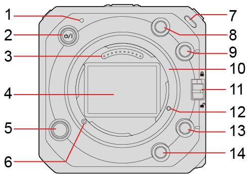
1Status indicator (Lamp / Indicator Display)
This displays the power status.
2[![]() ] Camera ON/OFF button (Turning the camera on)
] Camera ON/OFF button (Turning the camera on)
3Contact points
4Sensor
5Lens release button
6Lens lock pin
7Front tally lamp (Lamp / Indicator Display)
This will light when recording begins. It will also blink when the available recording time of the recording medium becomes short. When you do not want the lamp to light or when you want to change the brightness, you can set it on the menu screen. ([Tally Lamp])
8Fn button ([Fn2]) (Fn Buttons)
9Fn button ([Fn3]) (Fn Buttons)
10Mount
11Operation lock switch (Camera Setting Operations)
12Screw hole for function expansion
13Fn button ([Fn4]) (Fn Buttons)
14Fn button ([Fn5]) (Fn Buttons)
|
Top |
Bottom |
|
|
|
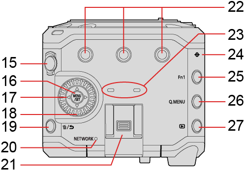
15Video rec. button (Recording Videos)
16[MENU/SET] button (Camera Setting Operations, Menu Operation Methods)
17Cursor buttons (Camera Setting Operations)
18Control dial (Camera Setting Operations)
19[![]() ] (Delete) button / [
] (Delete) button / [![]() ] (Cancel) button
] (Cancel) button
20[NETWORK] connection lamp (Lamp / Indicator Display)
Displays the network status.
21Hot shoe (hot shoe cover)
Keep the hot shoe cover out of reach of children to prevent swallowing.
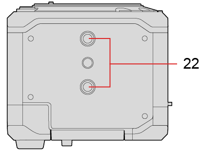
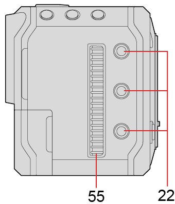
22Tripod mount
You can attach a tripod, platform or camera cage etc.
The size of the mounting screw is 1/4-20 UNC (Screw length is 5.5 mm (0.22 inch) or less)
If you attempt to attach a screw longer than 5.5 mm (0.22 inch), you may not be able to securely fix it in place or it may damage the camera.
23Stereo microphone
Do not block the microphone with a finger. Audio will be difficult to record.
24[![]() ] (Recording distance reference mark)
] (Recording distance reference mark)
25Fn button ([Fn1]) (Fn Buttons)
26[Q.MENU] button (Quick Menu)
27[![]() ] (Playback) button (Playing Back Videos)
] (Playback) button (Playing Back Videos)
Back
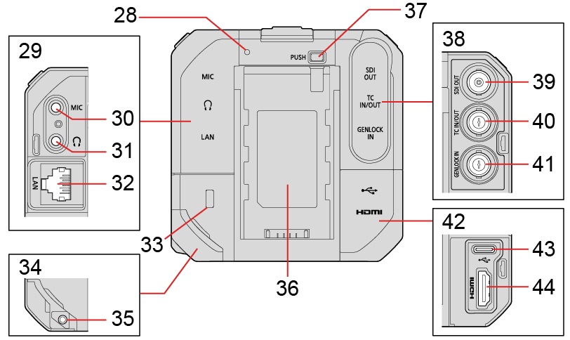
28Rear tally lamp (Lamp / Indicator Display)
This works the same as the front tally lamp. You can set whether to make the lamp light at the menu screen separately from the front tally lamp. ([Tally Lamp])
29AUDIO terminal cover
30[MIC] terminal (External Microphones (Optional))
This connects the external microphone.
31Headphone terminal (Headphones)
This connects the headphones for the audio monitor.
32[LAN] terminal
Supplying power from a PoE+ power supply. (Supplying power from a PoE+ power supply)
You can control the camera remotely by connecting with a PC that has the “LUMIX Tether” software installed. (Tethered Recording)
You can remotely operate the camera by connecting it with a LAN cable to the wireless access point to which the smartphone that has the “LUMIX Tether” software installed is connected to. (Connecting to a Smartphone (Wired LAN connection))
You can live stream the camera’s images and audio over the internet by connecting a PC installed with the streaming software and the camera to a router. (13. Streaming Function)
33Security Slot
Attaching anti-theft equipment can prevent theft. We are not liable for damages that may occur resulting from theft.
34DC IN terminal cover
Keep the DC IN terminal cover out of reach of children to prevent swallowing.
35Cable lock band attachment part (Attaching the Cable Lock Band)
36Battery attachment part
37Battery release button
38BNC terminal cover
39[SDI OUT] terminal (Connecting the external monitor)
This connects external monitors etc. and outputs an SDI signal.
40[TC IN/OUT] terminal (Preparations for Time Code Synchronization)
This connects with an external device and inputs/outputs a time code.
41[GENLOCK IN] terminal (Genlock settings)
This connects with an external device and inputs a sync signal.
42HDMI terminal cover
43[USB] terminal
You can control the camera remotely by connecting with a PC that has the “LUMIX Tether” software installed. (Tethered Recording)
Import shooting data by connecting with a PC. (Importing Images to a PC)
44[HDMI] terminal (Type A) (Connecting the external monitor)
This connects with an external monitor etc. and outputs a video signal.
|
Right side |
Left side |
|
|
|
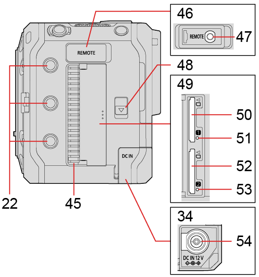
45Fan outlet
The fan outlet for the cooling fan. Do not block it when using this camera.
46REMOTE terminal cover
Keep the REMOTE terminal cover out of reach of children to prevent swallowing.
47[REMOTE] terminal (Using a remote control unit)
You can control a part of the function remotely by connecting the remote control unit (commercially available) to the camera. (A Panasonic shutter remote control (DMW-RS2) cannot be used.)
48Card door release lever
49Card door
50Card slot 1 (Inserting Cards (Optional))
51Card access light 1
52Card slot 2 (Inserting Cards (Optional))
53Card access light 2
54[DC IN 12 V] terminal (Supplying power with an AC adaptor)
55Fan Inlet
The fan inlet for the cooling fan. Do not block it when using this camera.